MARLON GARCIA
HP
Description
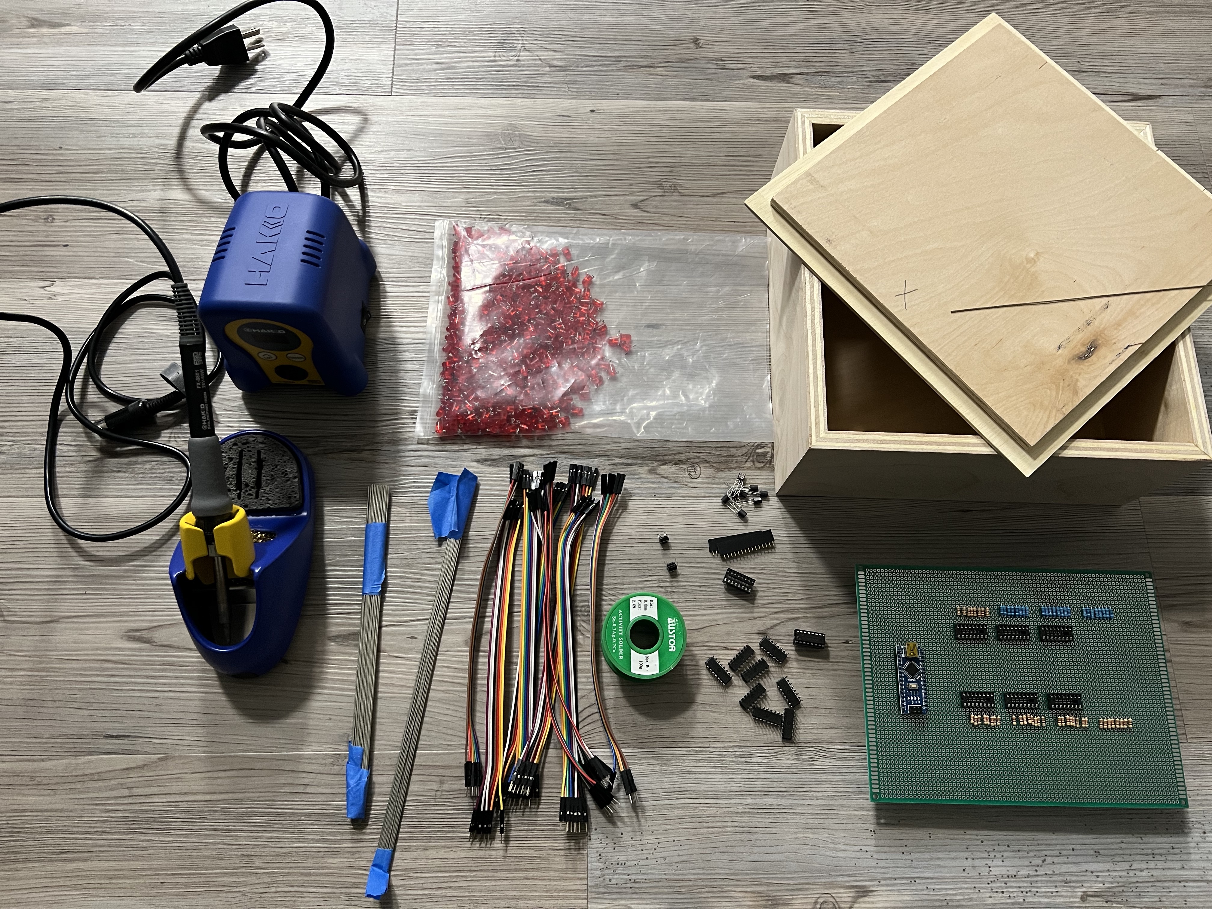
Materials and Enclosure
- Soldering Iron Kit
- 1 arduino uno.
- 512 red LEDs
- 64 150 ohms resistors
- Galvanized wire
- Solder Wire
- 9 shift registers 74hc595
- 1 chip (uln2803)
- 9 ic sockets of 16 pins
- 1 ic socket of 18 pins
- PCB Board
- Jumper cables (approximately 70)
- 1 momentary button
- On and off switch
- 5 volt power outlet
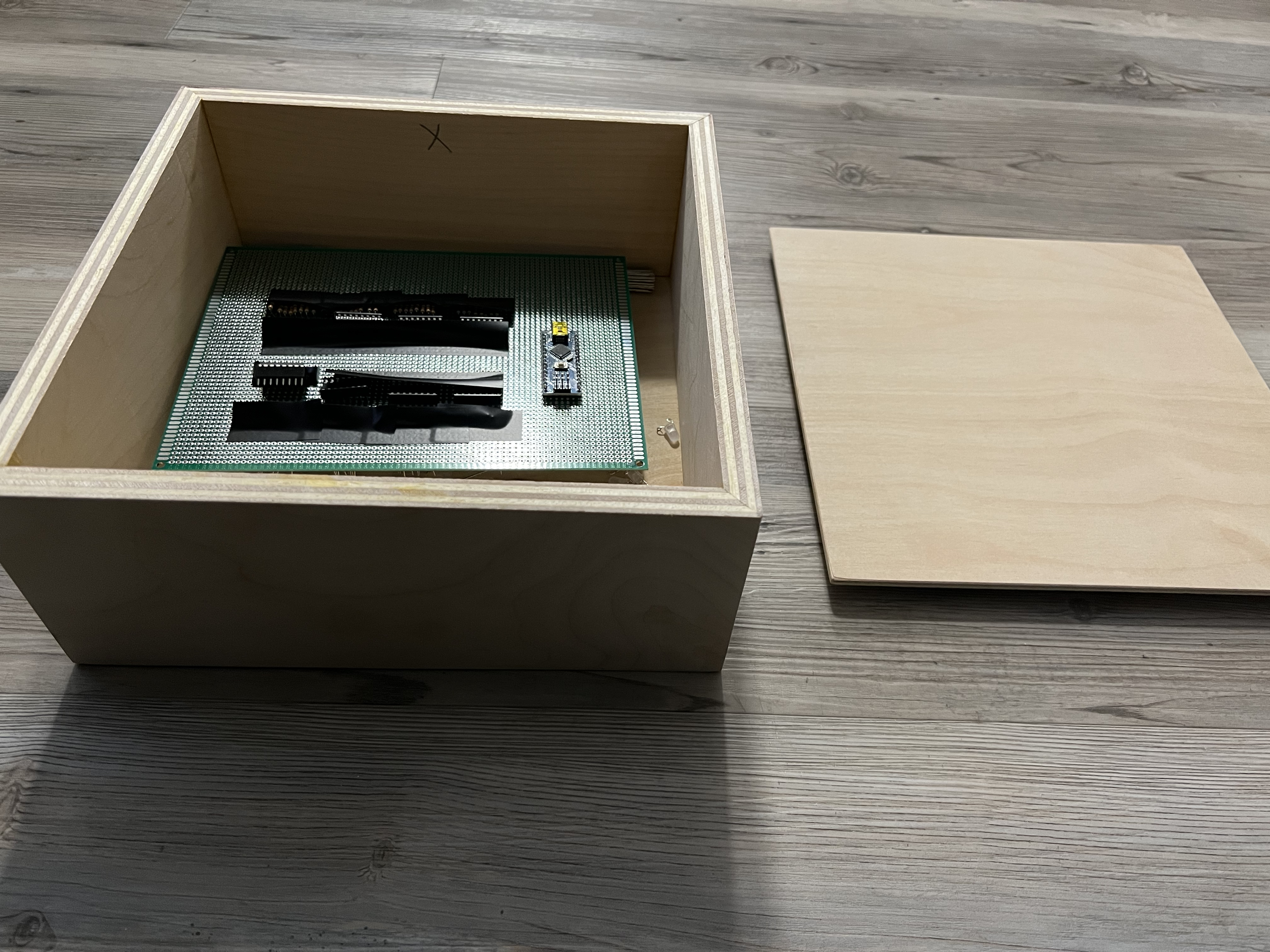
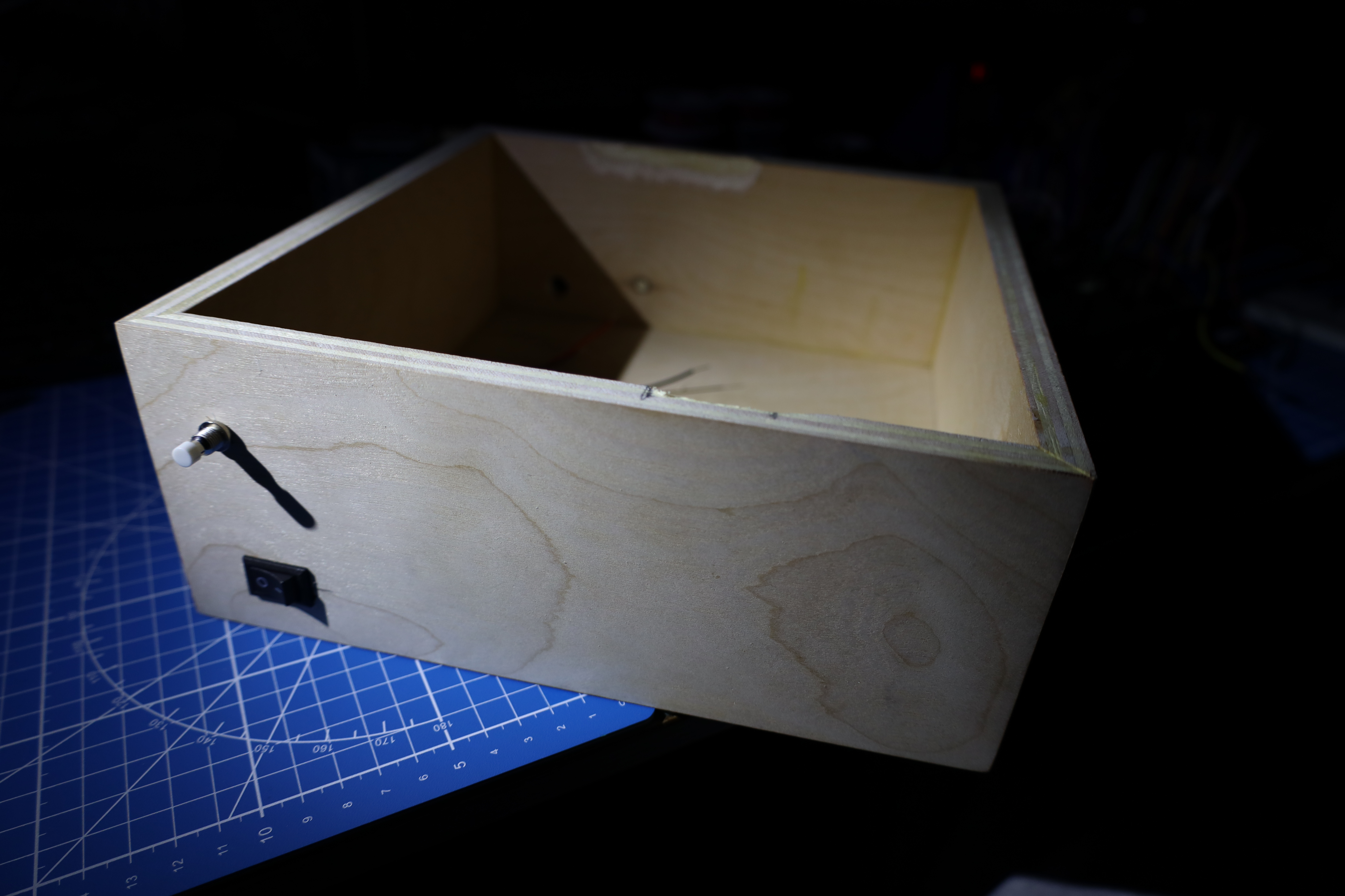
Close up look at the enclosure for all the hardware of this project.
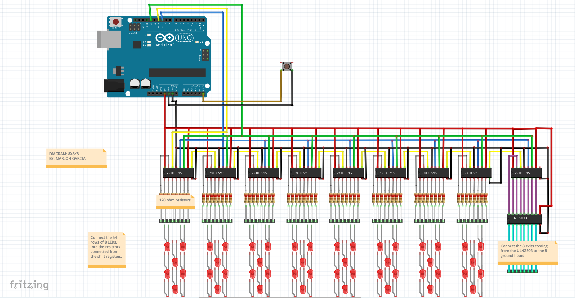
Diagram
This diagram allows me to see where connections need to happen, how
arduino uno connects with either solder wire or jumper wires sending data
from the chip itself to the shift registers and the ground levels to the
LEDs and successfully sending data.
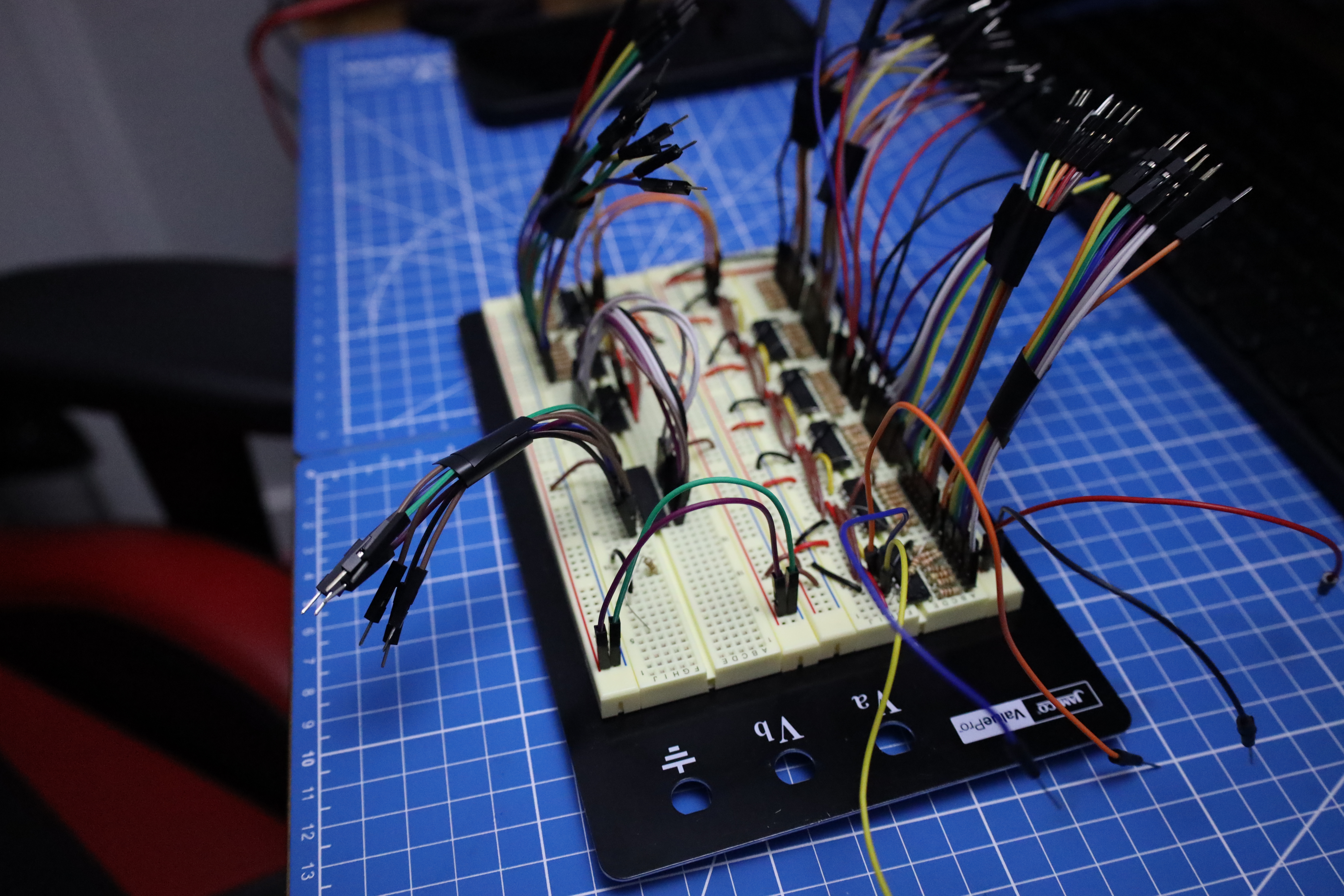
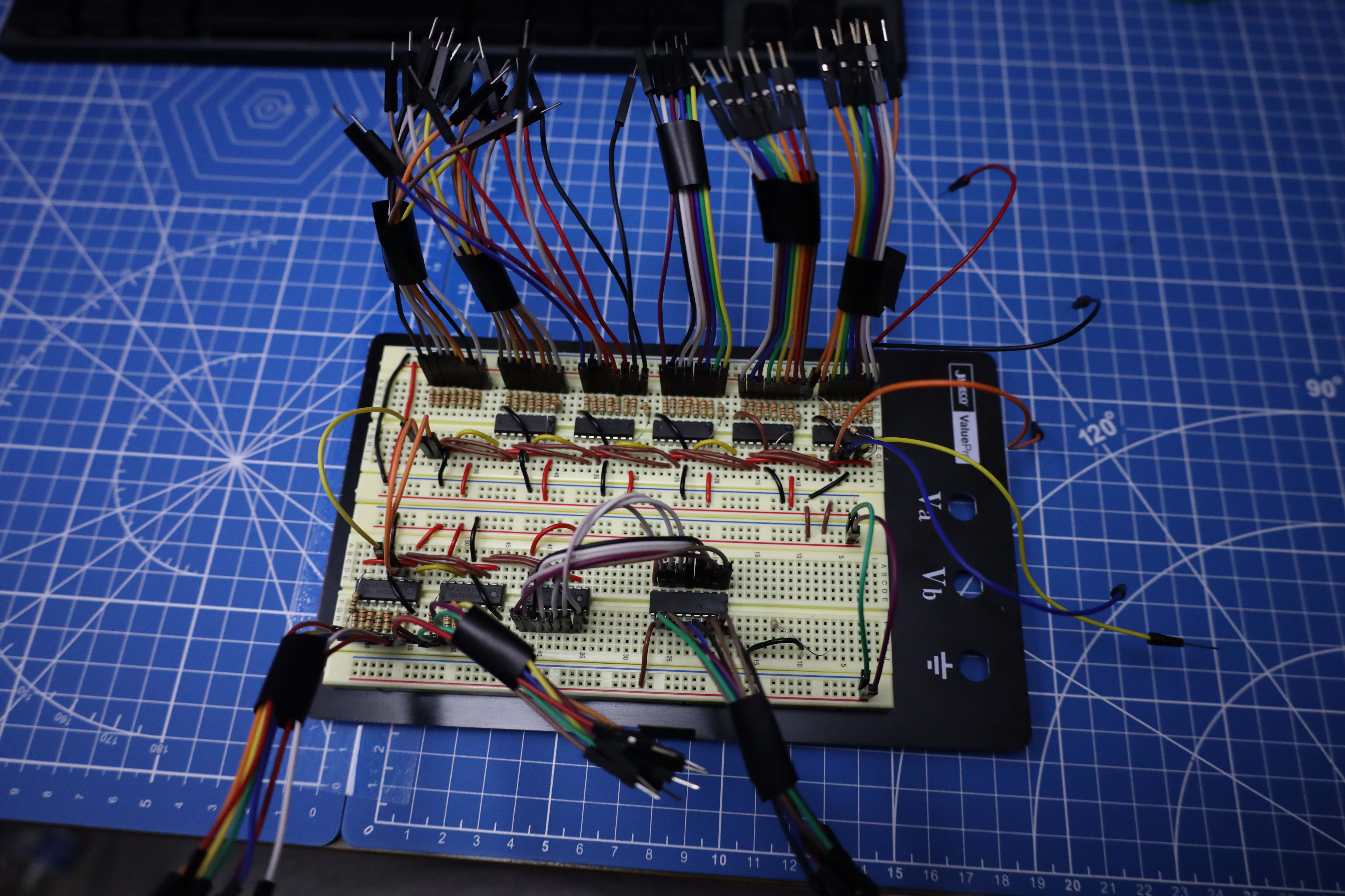
Prototype
In this phase of my project I used a breadboard to make every single
connection following the diagram below and making sure the project was
functionable. In this state I tested LEDs in order to verify that arduino
was sending data and LEDs were functionable.
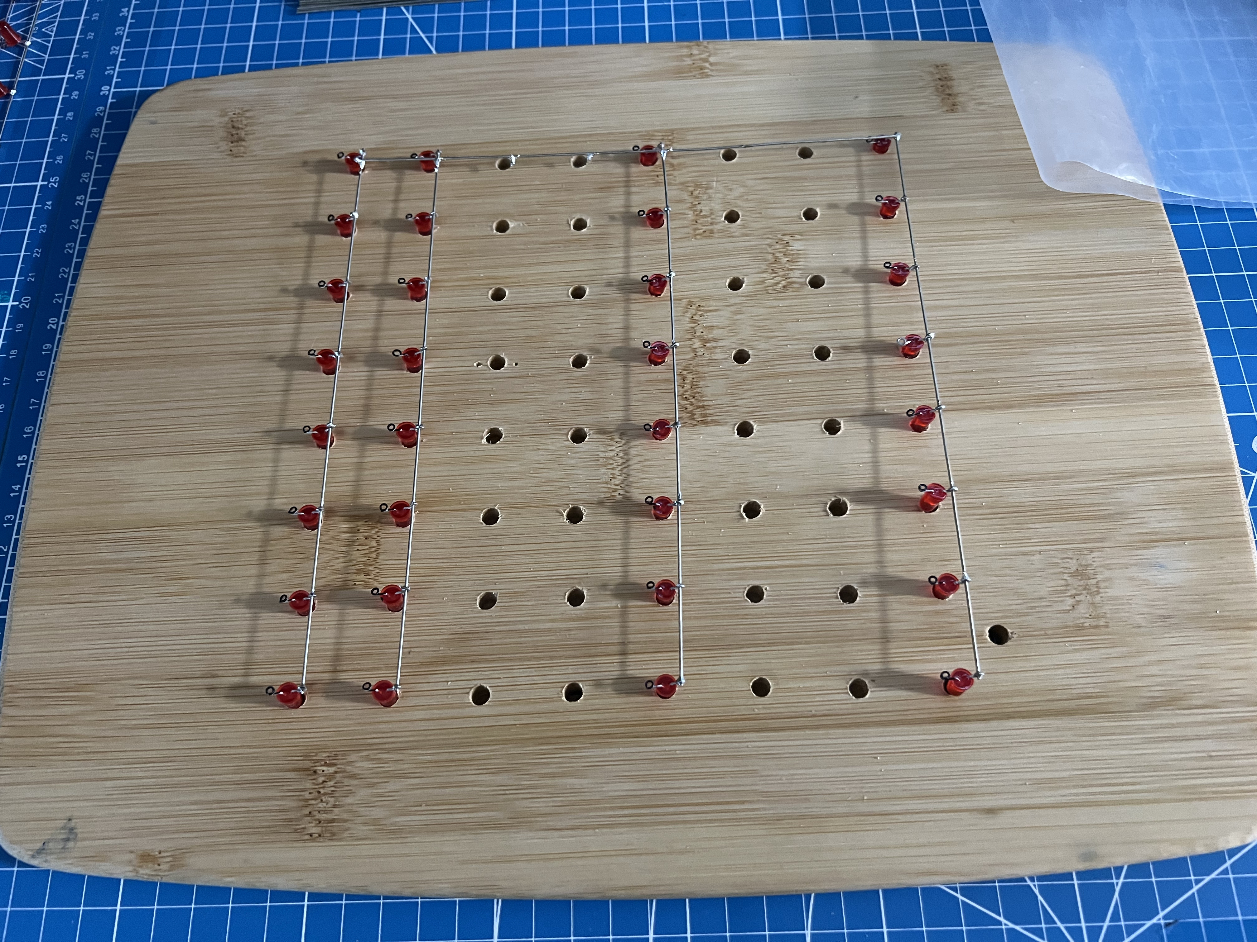
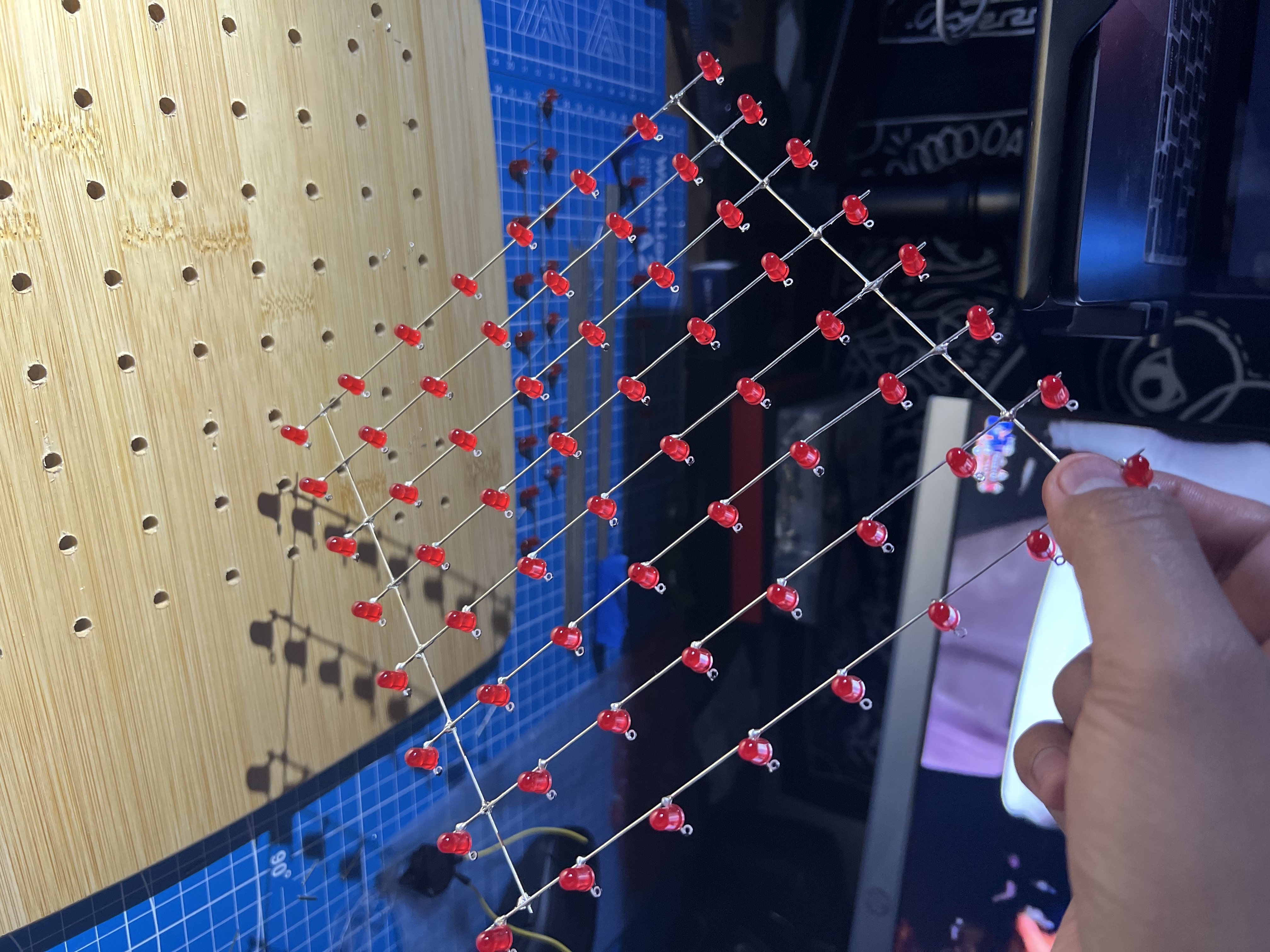
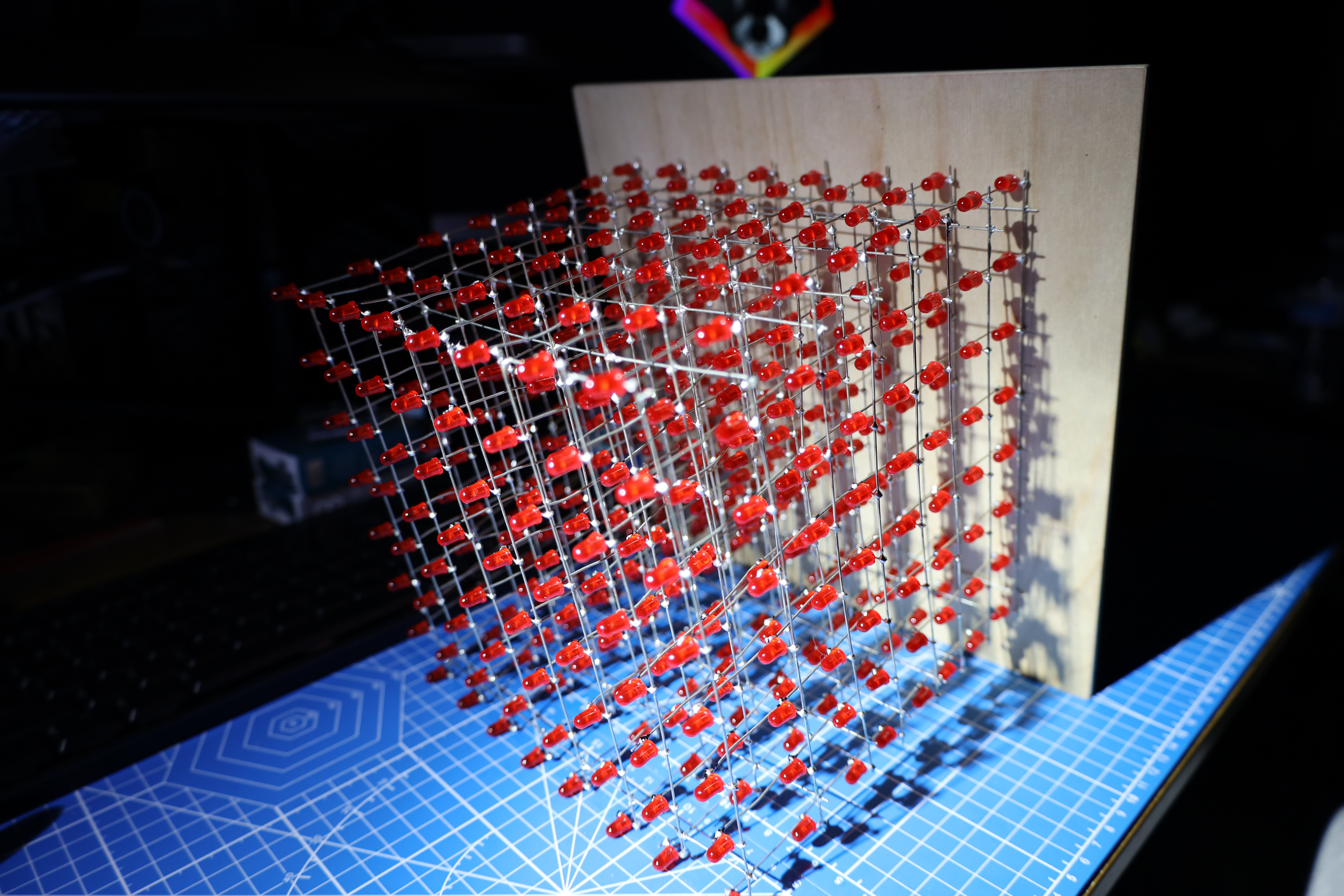
Working Progress
After Figuring out how everything was going to be assemble it was time to
start making the 8x8x8 cube, at this point there was only a matter of
patience and lots of soldering. The way the cube was made was, created a
grid of 8x8 of 1 inch apart from each whole and put every LED in one of
the holes. I also took some time making the negative and positve leg of
each LED round so I could facilitate my work when I was about to start
soldering the LEDs.
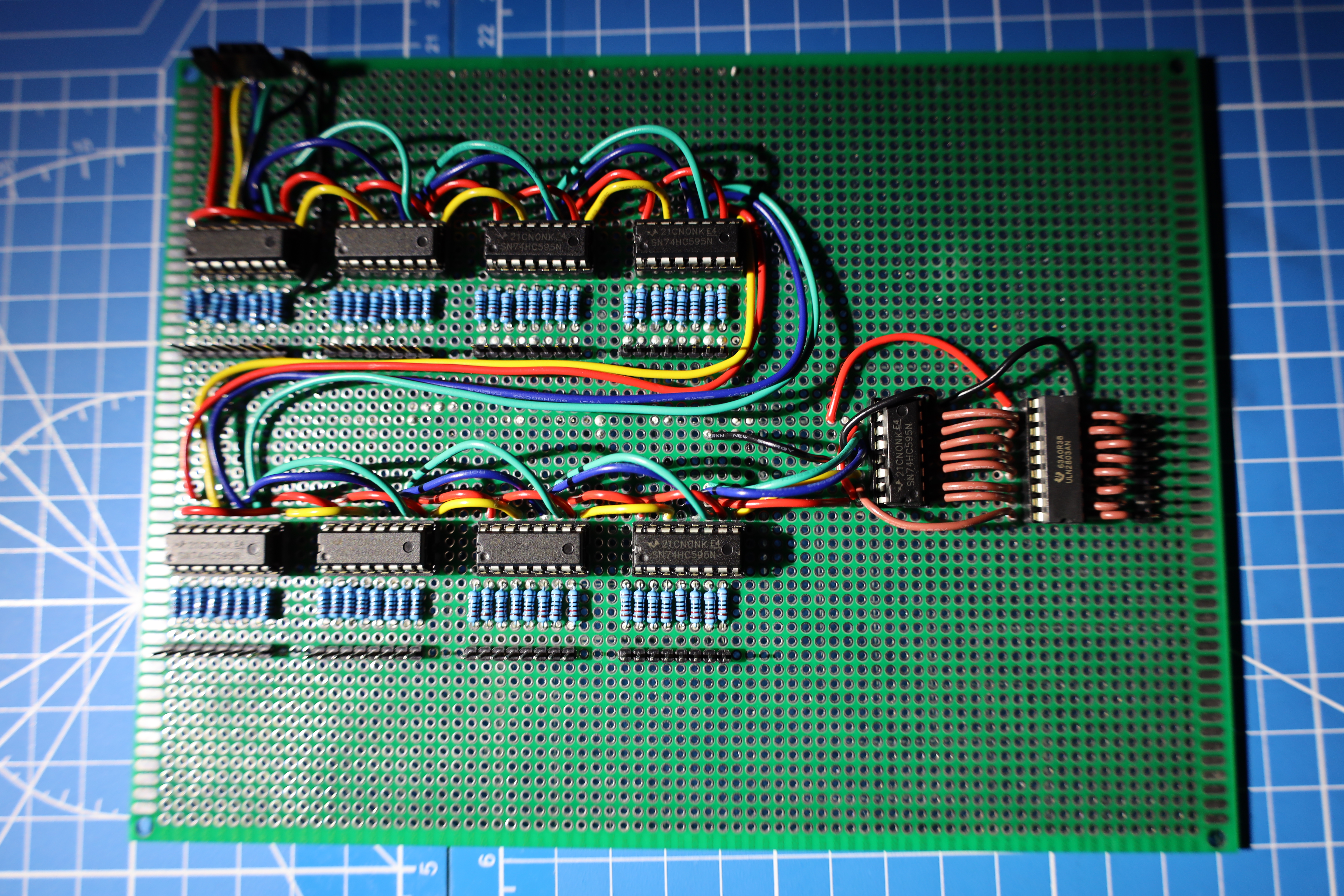
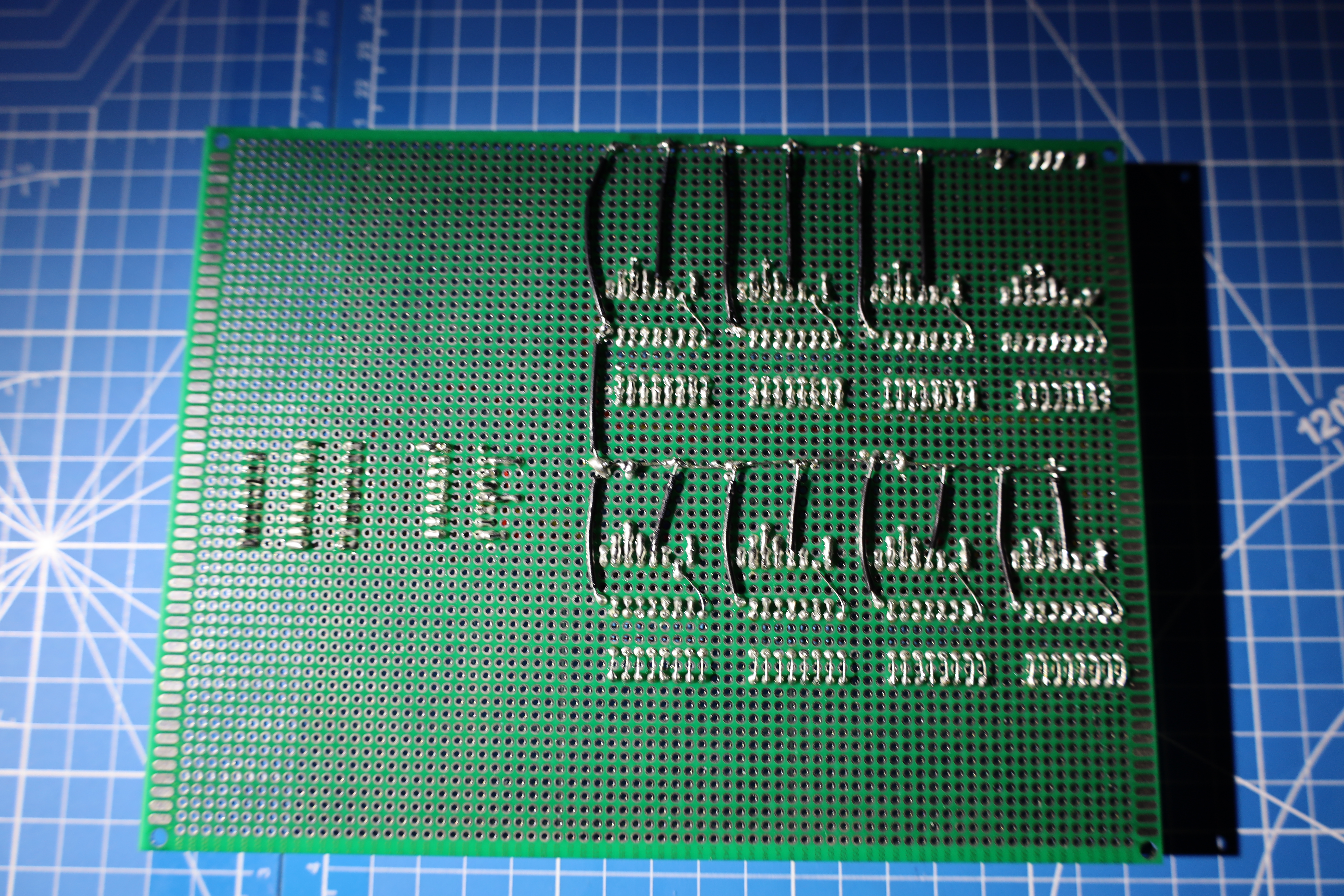
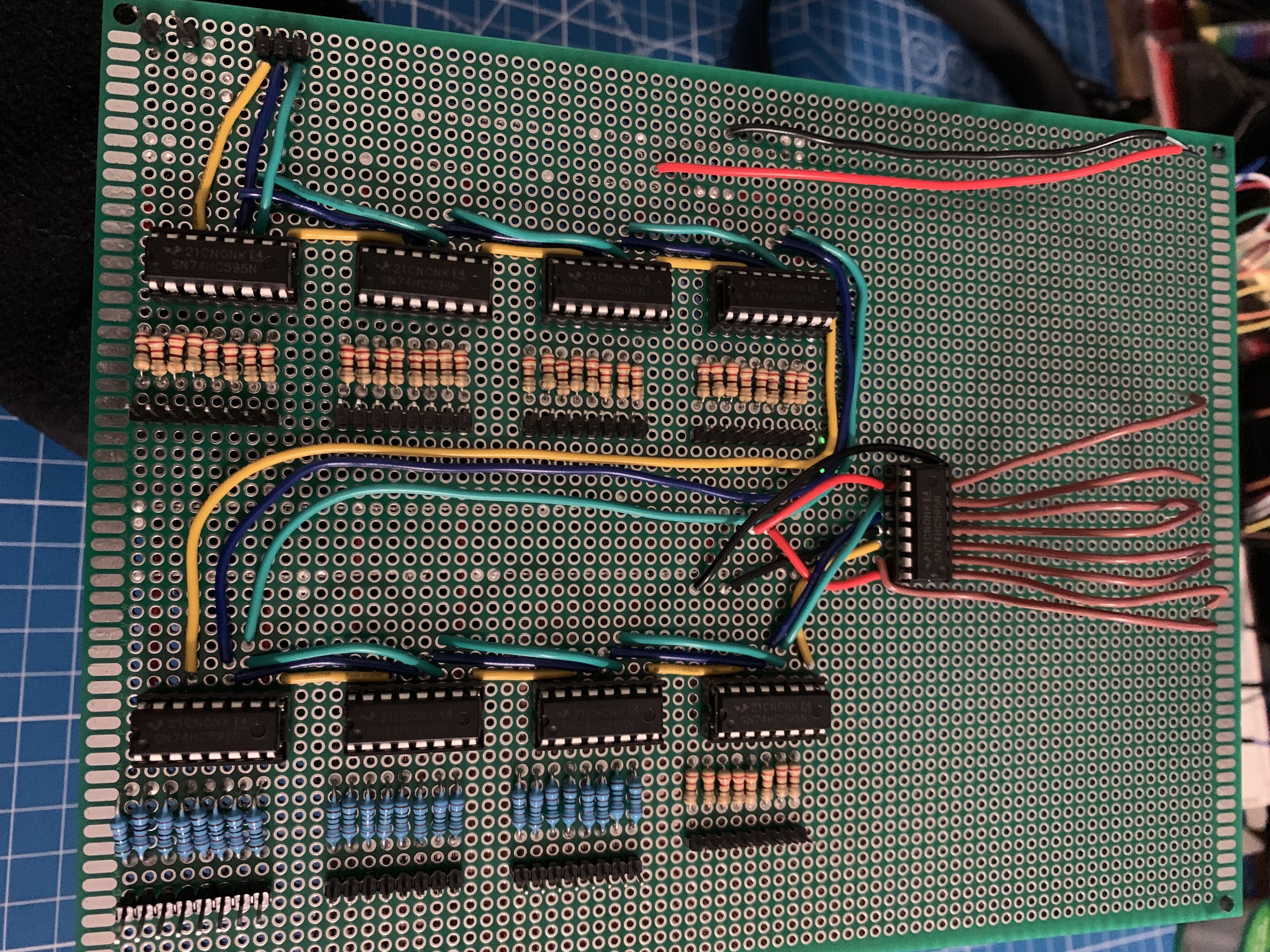
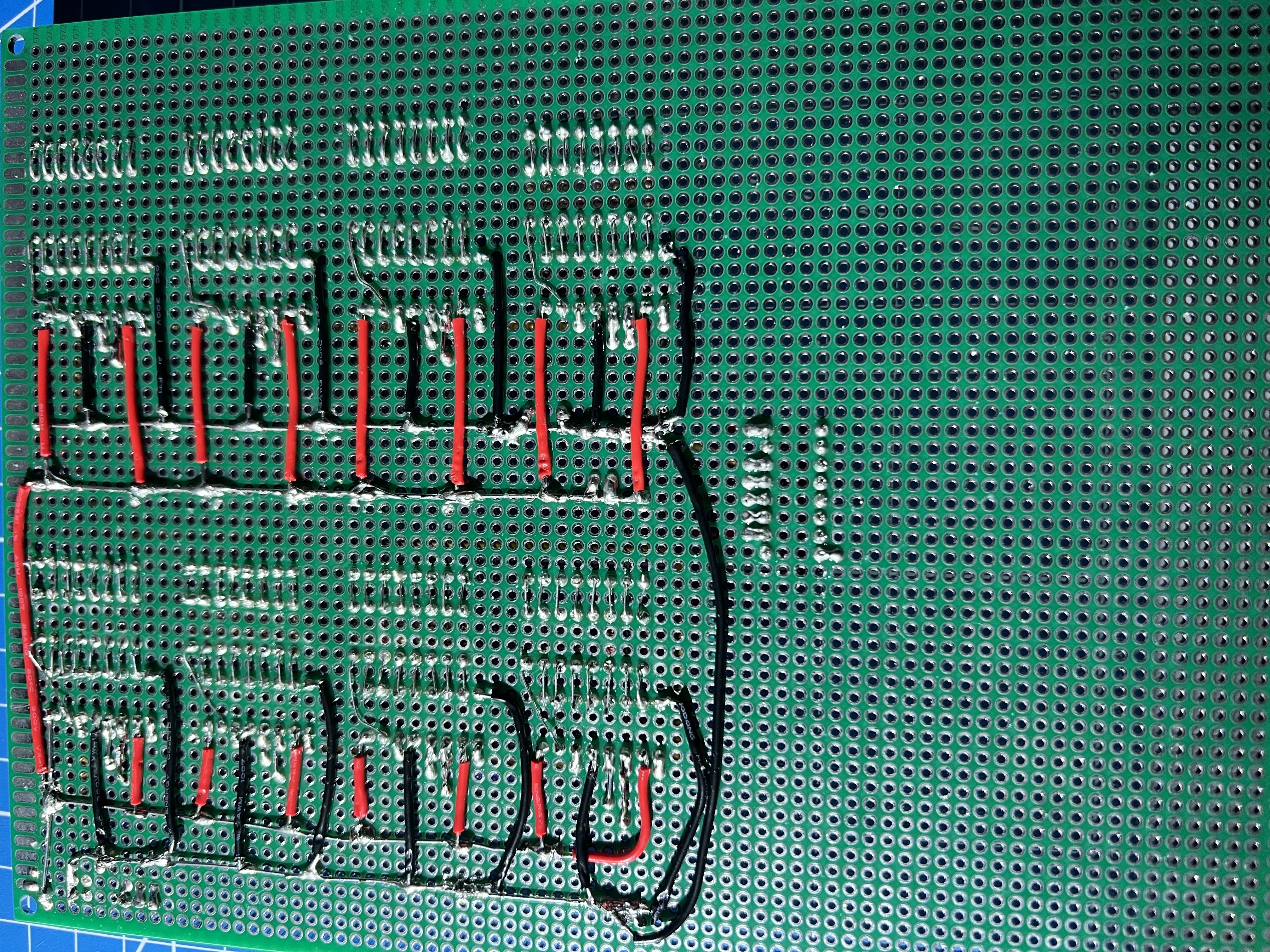
Soldering PCB Board
At this stage of the project, with the help of the diagram, I was able to
solder the PCB board, every connection was verified with a multimeter, no
bridges were created on the conncetions made. There was one line for
ground, one for volts, one for datapin, one for the clockpin and one for
latch pin. There was also connections on every resistor and also
connections to the 8 ground floors and the 64 positive LED rows. IC
sockets of 16 pins were used to mount the shift registers 74hc595 and one
ic socket of 18 pins to connect the uln2803.
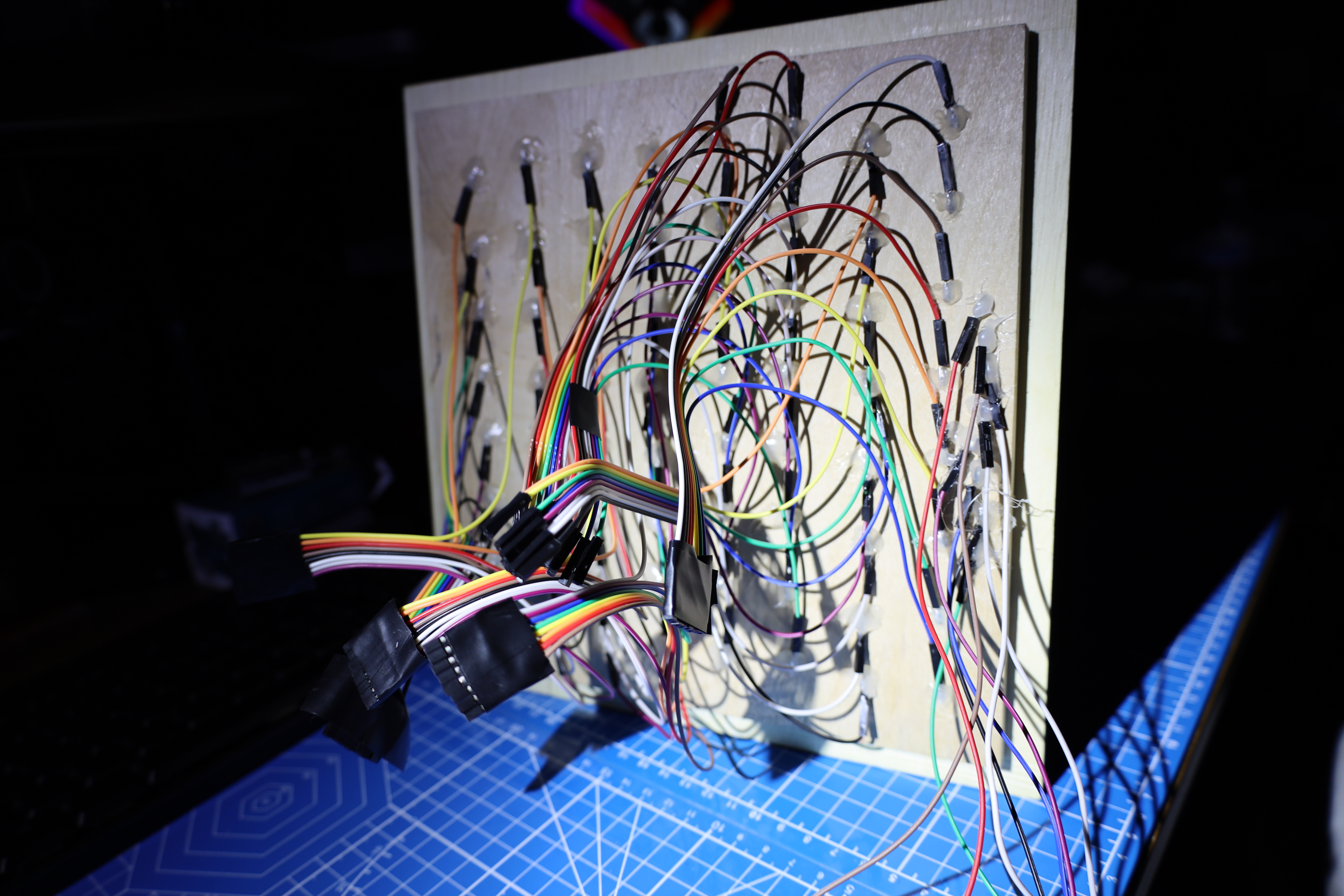
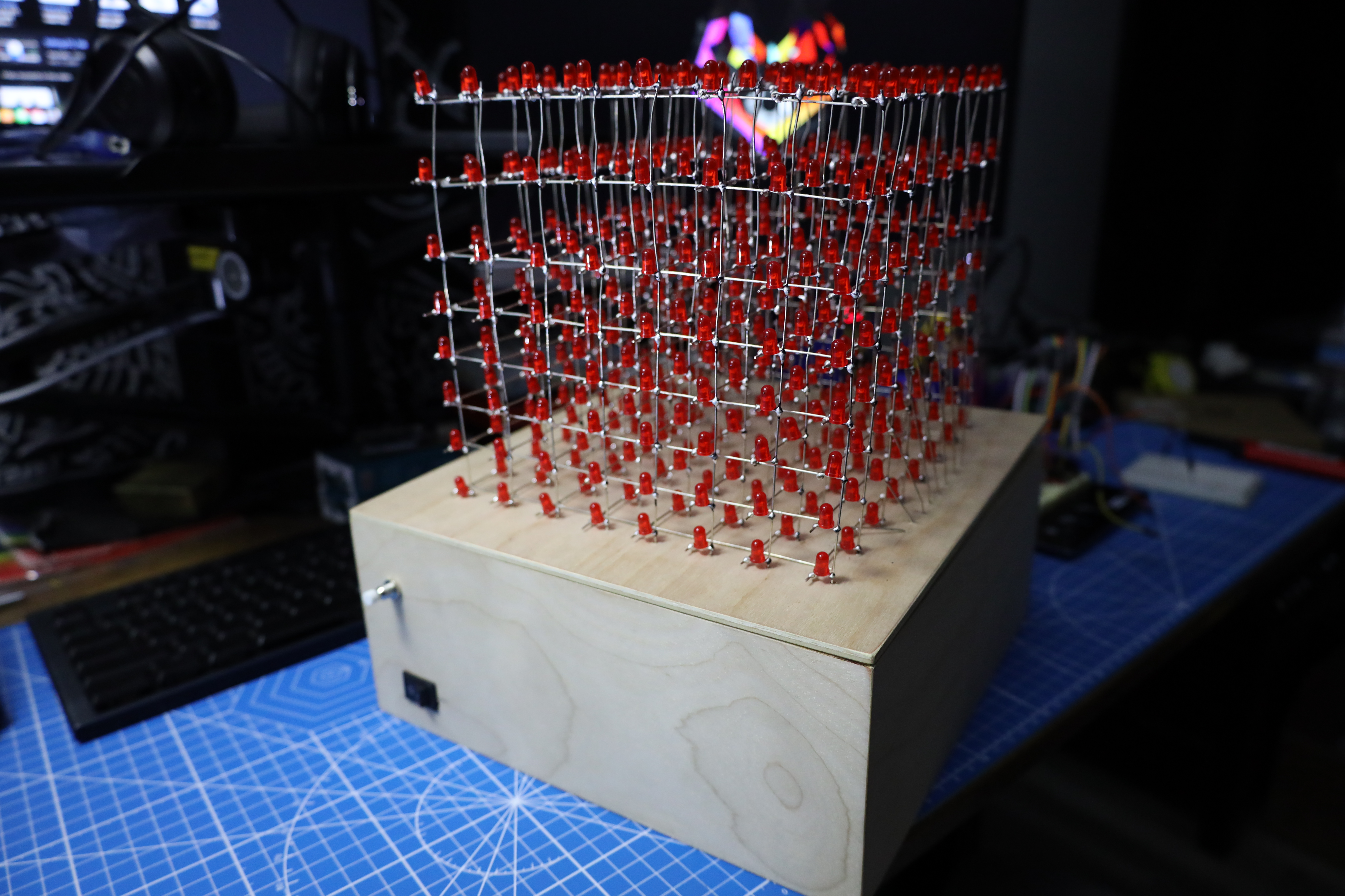
Finished Cube and Connections
After a long soldering process, The cube was finalized and mounted into
the lid of the enclosure, in the second image we can see the connections
to every single positive exit of the 64 rows of 8 LEDs coming from the
top. Everything was kept as clean as possible and organized so it wouldn't
create any confusion when connecting every cable into the finished PCB
Board.
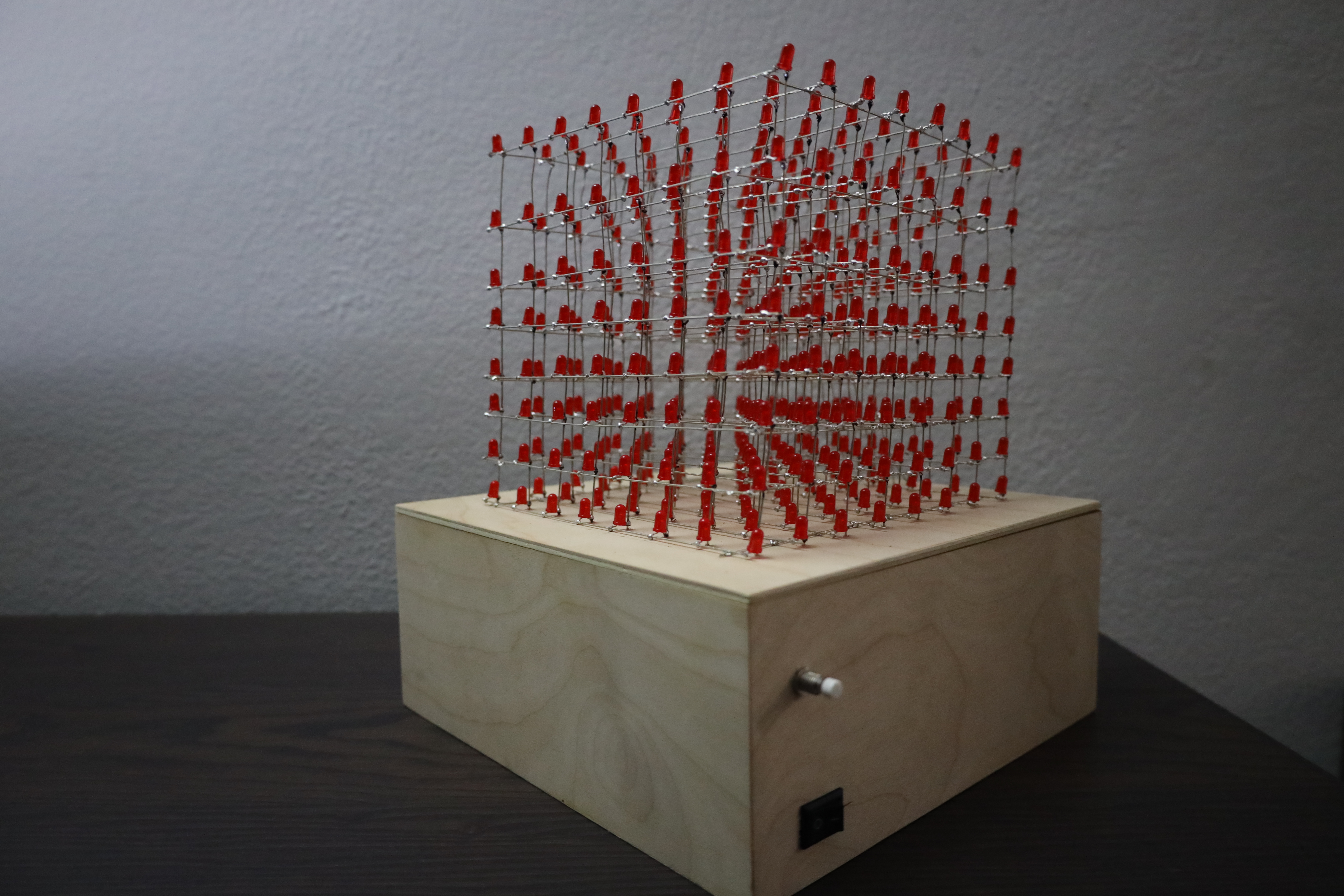
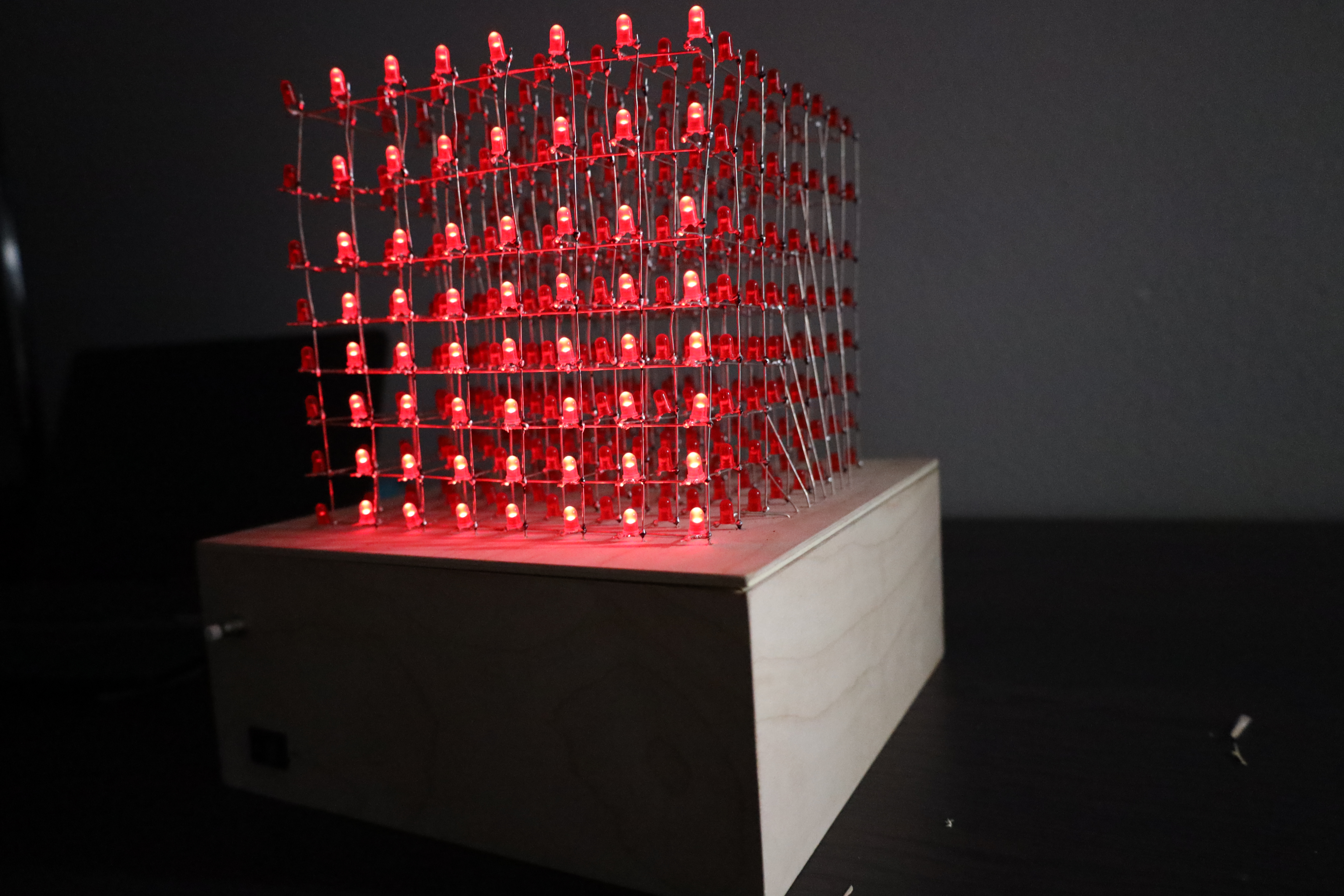
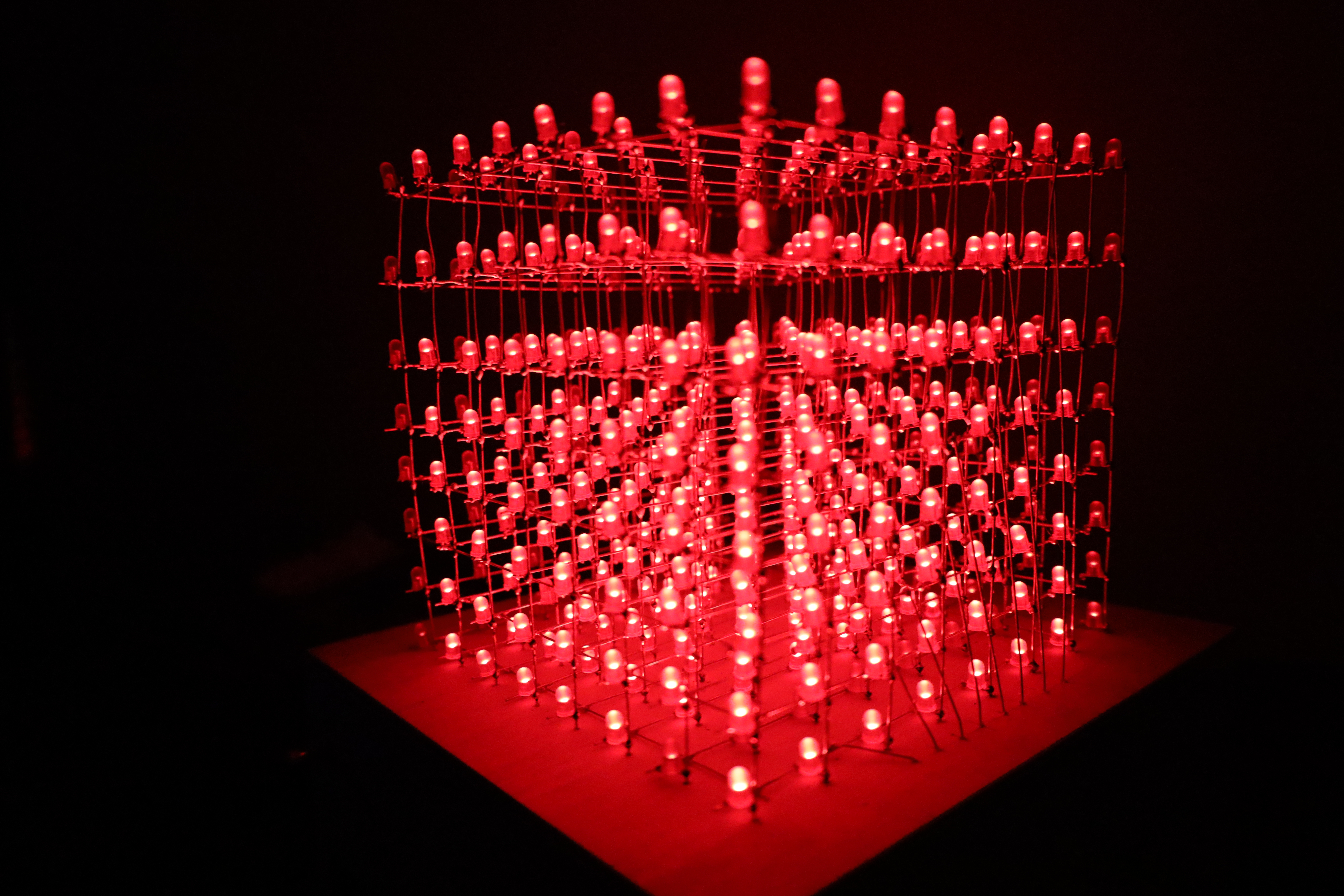
Finalized Project
In the final phase of my project, we can finally see the finished piece,
on the left image we can see the cube turned off but with the right amount
of lighting that displays every single detail of the cube and box. On the
second image to the right, we can see the cube and the enclosure in a
different angle.
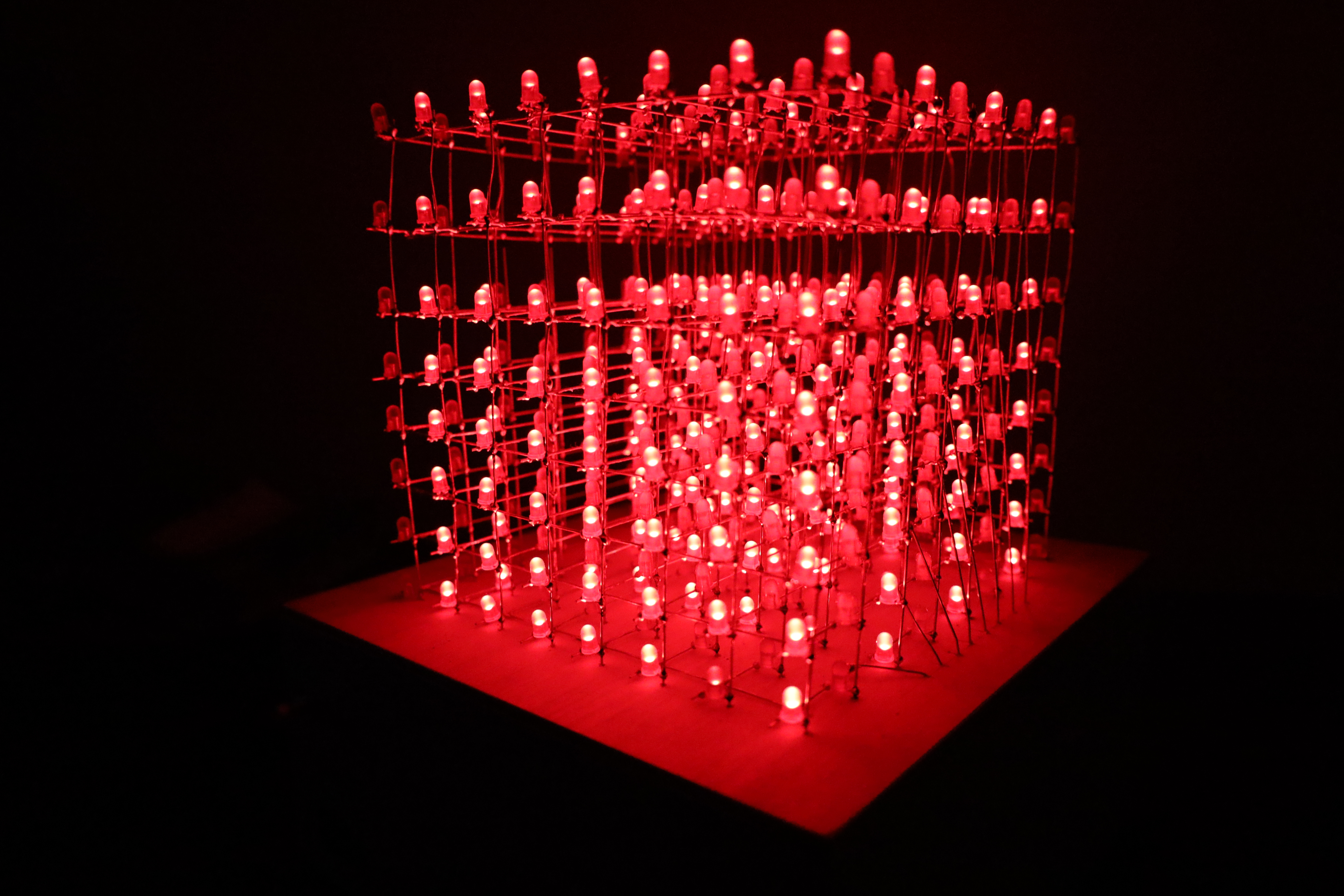
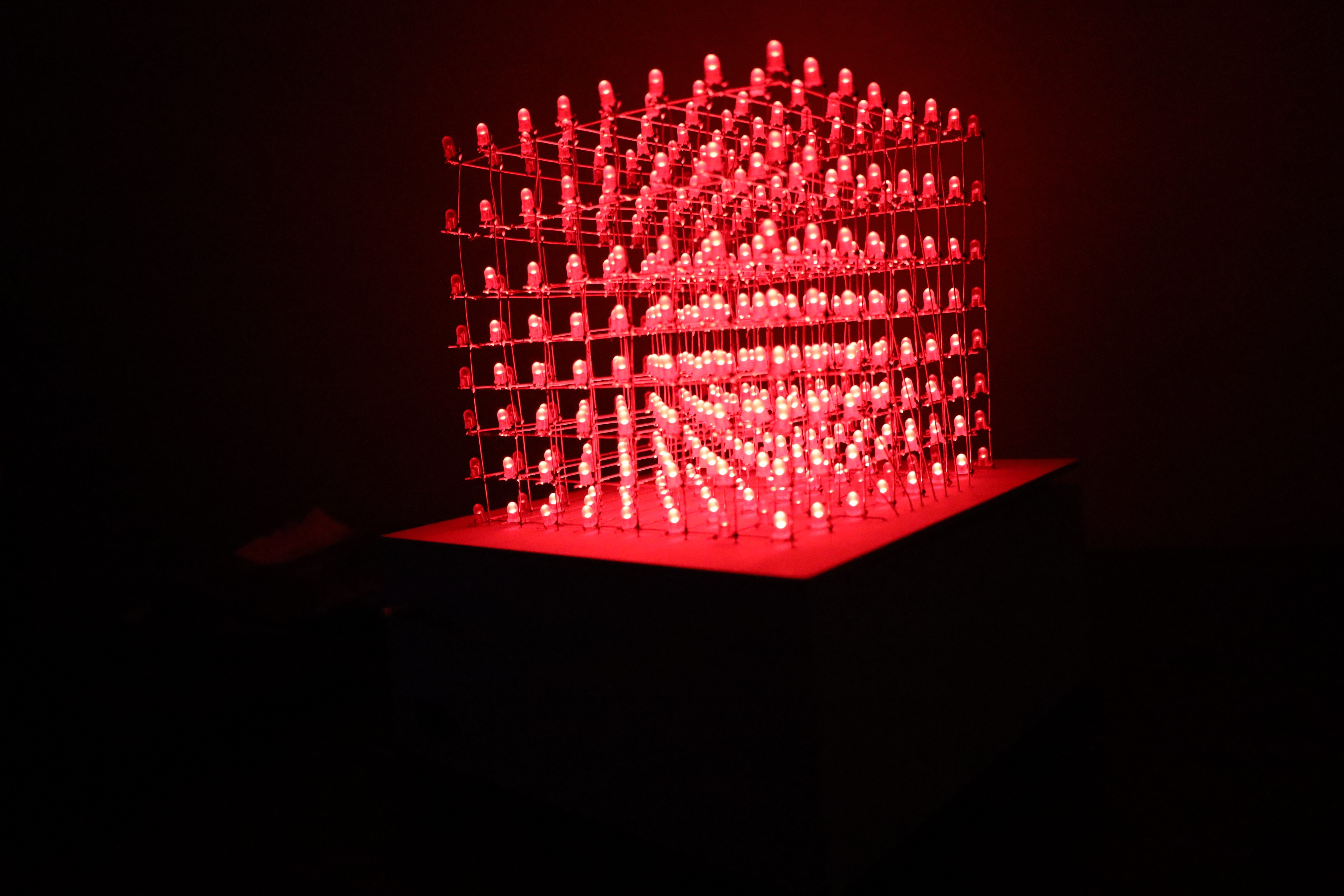
Finalized Project 2
In the end of this project we see four differnent images that display
different designs on the lighting. Different angles and different lighting
to see the difference in space and lighting that the LEDs create.
Final Project Video
After roughly 50+ hours of work, I can happily say I achieved what I was
looking for when thinking what I wanted to make for my graduation project.
I overcame many obstacles, shear some tears when things were not going the
right way, rebooting, resoldering, and tons of dedication in order to
achieve my goal. I am happy to say that my stay at SJSU has given me the
ability to create things I never thought I could. This project also
represents what I initially wanted my project to represent. Nolstalgia
played a huge role not only here but in most of the pieces I creat myself.
I am a true believer that practice makes perfection and this project is a
clear example of it.
---Issues I found while making this project---
While making my first soldering PCB Board, I never checked any connections
with a multimeter and that was my biggest mistake in this project, I
created bridges from the ground connections to the 5 volt connection and
every time I tried connecting the cube it was overheating and at some
point, the power outlet was smoking. I lost roughly 5-10 hours of
soldering work with this mistake. Using a multimeter will save you time,
mistakes and frustation.